My DIY low budget electric boat project;
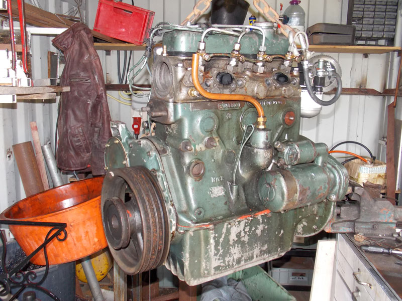
I'd just finished rebuilding the 50 year old Mercedes diesel engine when the new policy was announced.
Amsterdam has initiated a clean air policy that will ban all fuel burning transport in the city center; punitive costs for diesel boats are already in place in 2020 and soon fuel burning propulsion will be banned.
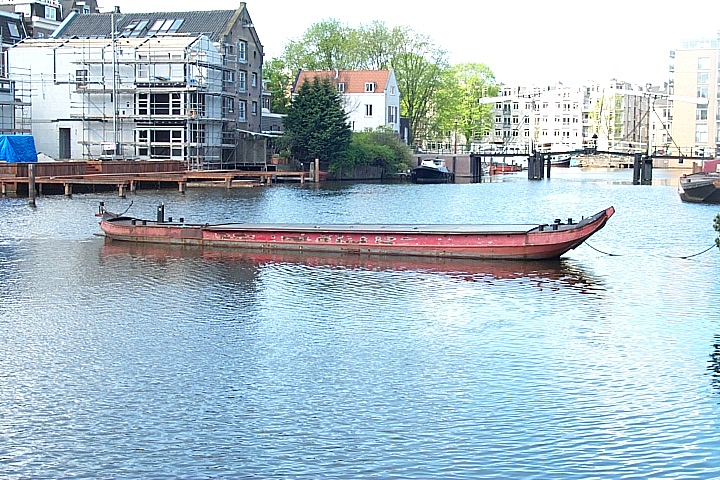
My workboat is 100 years old, a classic 14 meter Westlander that weighs 12 tons or more.
To be permitted to moor in the city at all, propulsion is required.
The maximum speed for transit through town [inner canals] is 6kph. This boat needs 5-6 HP to cruise at that speed. I need more for stopping and turning though.
Suitable motors are available, with control [but no battery or charger] they cost 5,000 euros and up.
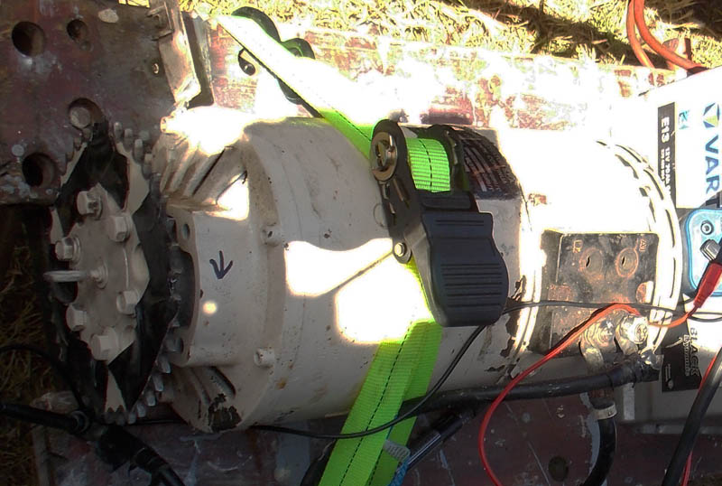
I saw a second 12HP forklift motor with a semi-modern electronic control for 350 Euros.
Probably a mistake, but once the ball was rolling there was no way to stop it.
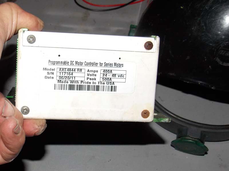
Although the box says 500A, continuous rating is less than half that, depending on cooling.
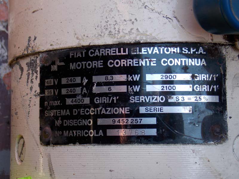
After getting it all back to my workshop, I translated the motor plate and realized that the motor has a 25% duty rating; that is 10 seconds on will need 30 seconds off or it will overheat.
Although I'll mostly use it at 1/2 power, getting the 14 meter 12 ton boat around a canal intersection will need all it has for a minute or two.
Some internet EV pundits said a bigger fan would be all I need, but I've learned to trust my own judgment on these matters. The motor is very small for 10HP. Efficiency is arond 0.86, the rest is heat that has to be dissipated at a temperature low enough to avoid damage.
I decided on water cooling the case as well as adding a larger fan.
My first idea was to make a stainless replacement case but I was unable to source the material. I went with regular mild steel and it will be cooled with a glycol solution and a heat exchanger; since those parts are already in the boat.
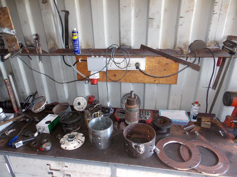
On my workbench in Portugal; controller, 'new' large squirrel cage fan, the AXE control, the descaled motor case, and the water jacket parts.
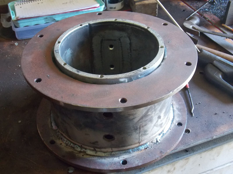
The original Bosch motor case surrounded by the water jacket I added, not finished welding yet.
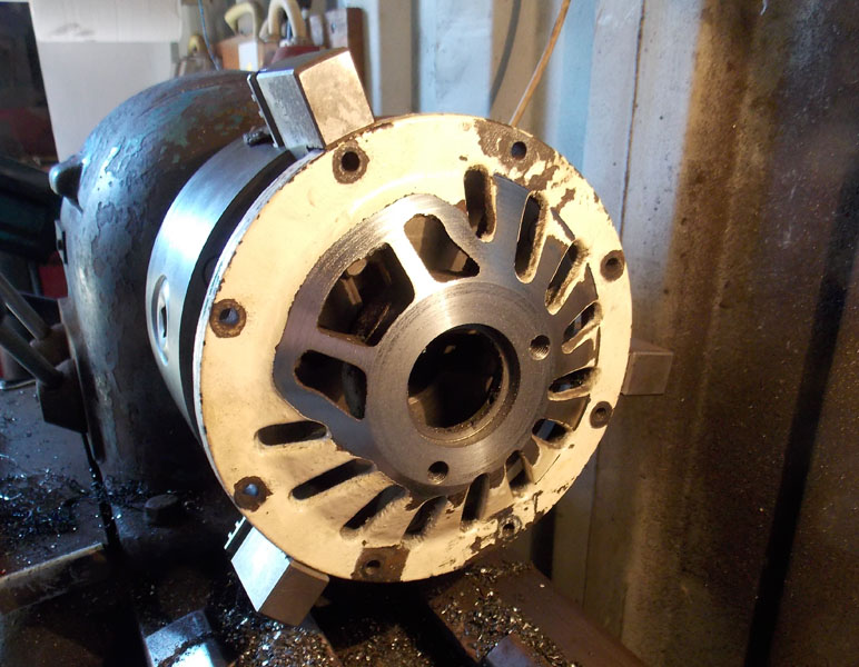
This is the end cover of the motor with mounting for bearing and the hydraulic pump it was made for. Mounted on my ancient lathe.
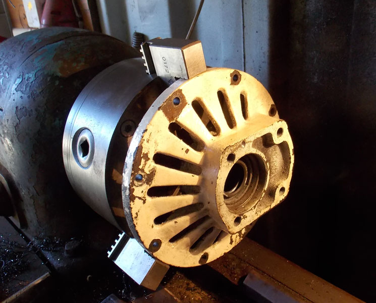
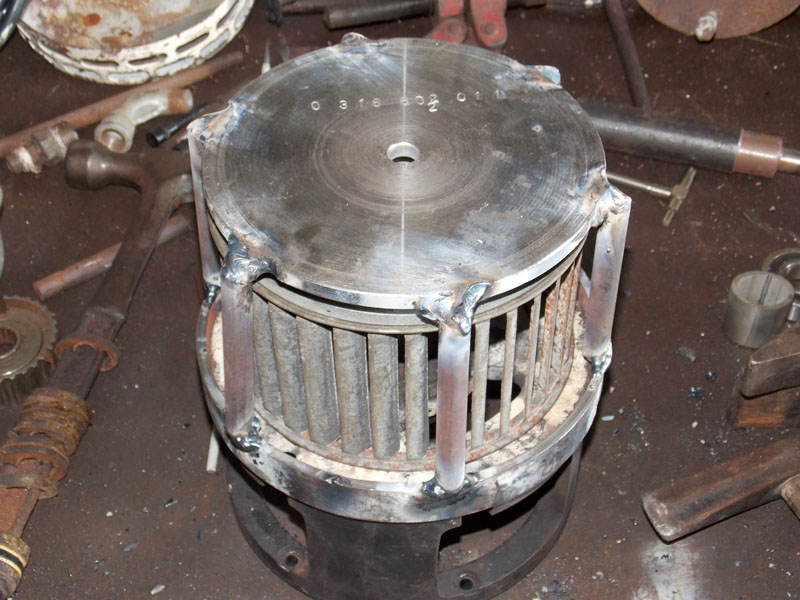
And here it is after I cut it down, with much greater air passages and less clutter.
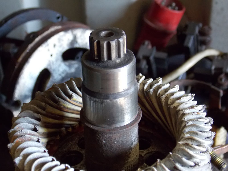
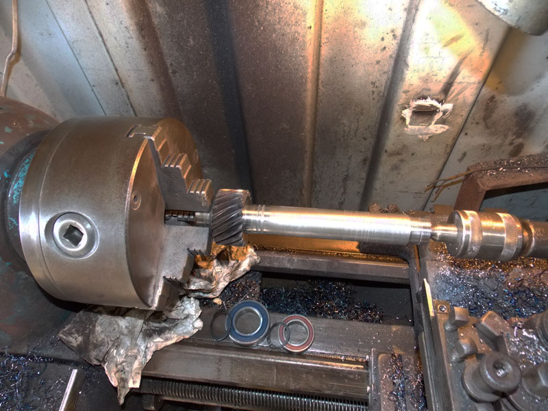
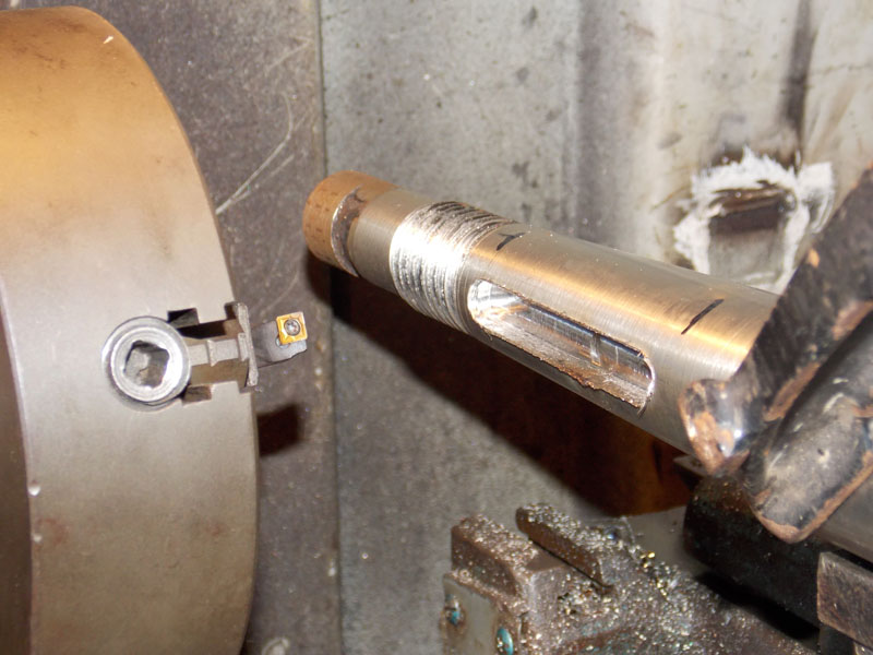
The armature has only a short spline for the load; I added this collar to the flange that came with it [it was used for a go cart] so it will press on fairly hard now and be reasonably secure.
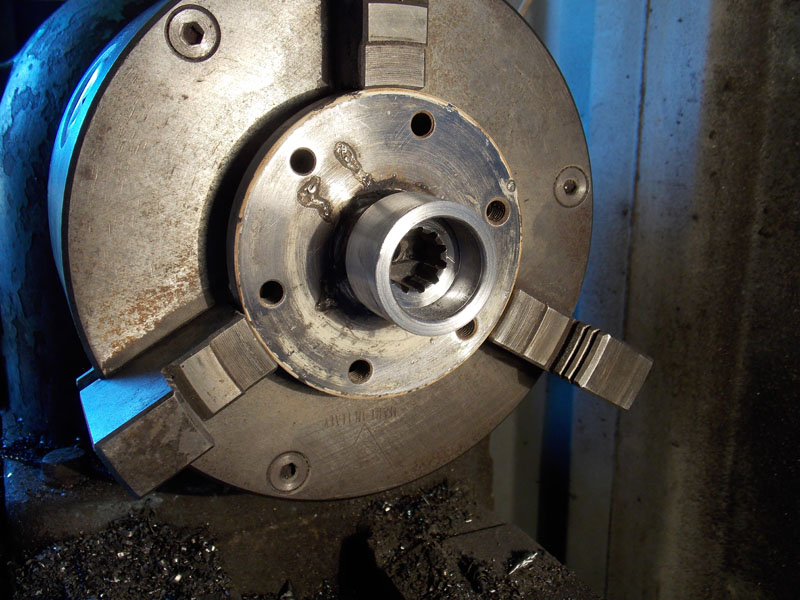
The smooth section of the shaft just below the spline was for an oil seal, will now be for the press fit colar.
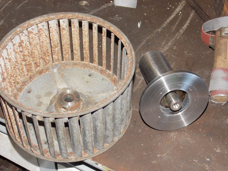
I sacrificed a good 1/2HP blower to get this fan cage for the boat motor. I hadn't found any use for it for 15 years anyway. It has about the right characteristics, but was made to mount from the other side. So I made this adaptor to press onto the tail end or the motor armature where the small original fan was.
The fan protection cage; I'm not really happy with it. A bit ugly.
I stamped the bosch motor number into it, because the case is now welded into the water jacket.
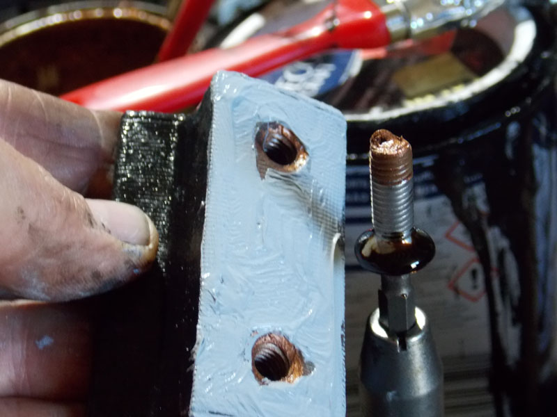
This is one of the field coil armature blocks; I've added heat conduction grease to carry heat from the coils into the case, where hopefully it will be carryed away by the cooling water. On the mounting screw is copper grease to prevent corrosion and Permatex gasket sealent to stop water from leaking into the threads.
The challenge is to stop the roating armature from overheating, which I can't cool directly. By keeping the case as cool as possible and increasing airflow, I hope the rotating armature will stay cool.
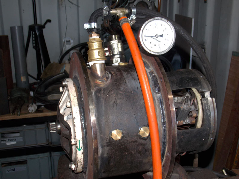
Partly assembled, filled with water and with a little pressure added for leak testing. No leaks.
The brass plugs cover the holes where the field coil armature screws are fitted through the inner original motor case.
This steel box will be in the cooling water flow, the AXE control box screws to the machined surface with a layer of heat sink grease between. I think this will keep the electronics happy. 1/2" pipe fittings are stainless.
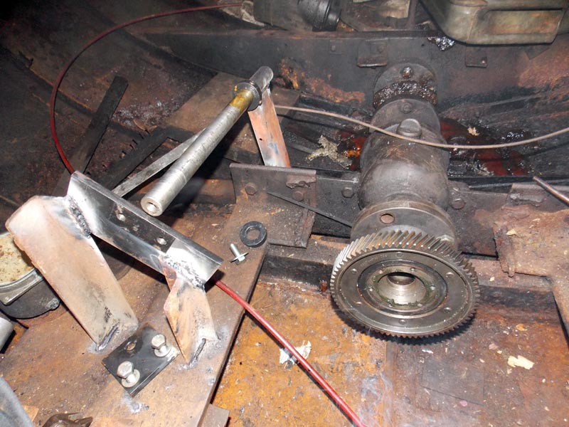
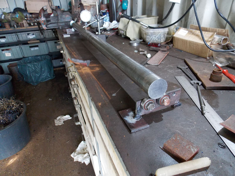
The subshaft; this will be driven by a reduction pully set on the motor, and drive a large gear on the propshaft thrust bearing block. 3.8:1 Gears are from a junk car gearbox I've had lying around for a long time.
I need 5:1 reduction and the geometry just doesn't work out with a single gear set.
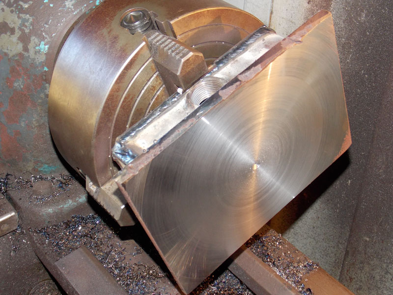
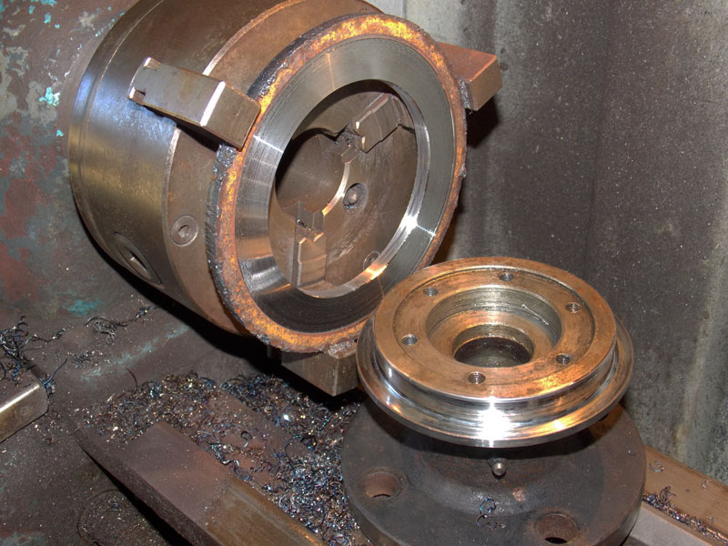
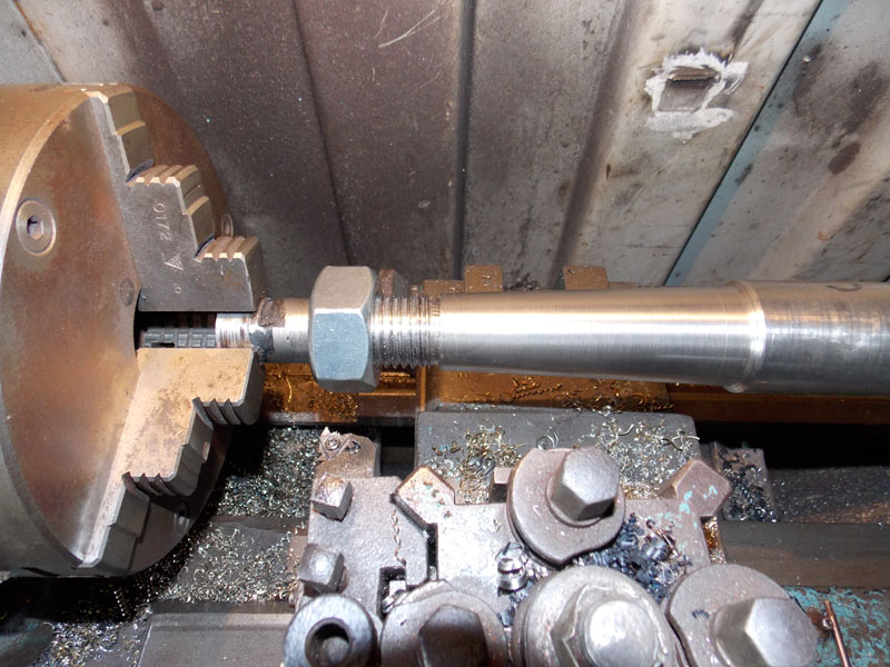
At the bottom of the photo, the old fitting from the boat, in the lathe chuck I'm turning a flame cut plate to make a flange that will fit the large driving gear. It will be welded together and then trimmed in the lathe again.
The gears and belt pulleys lined up on the bench. Tricky because it has to have clearence for the drive shaft for the diesel motor too.

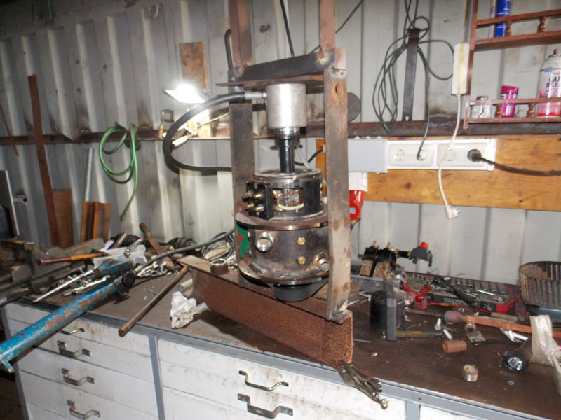
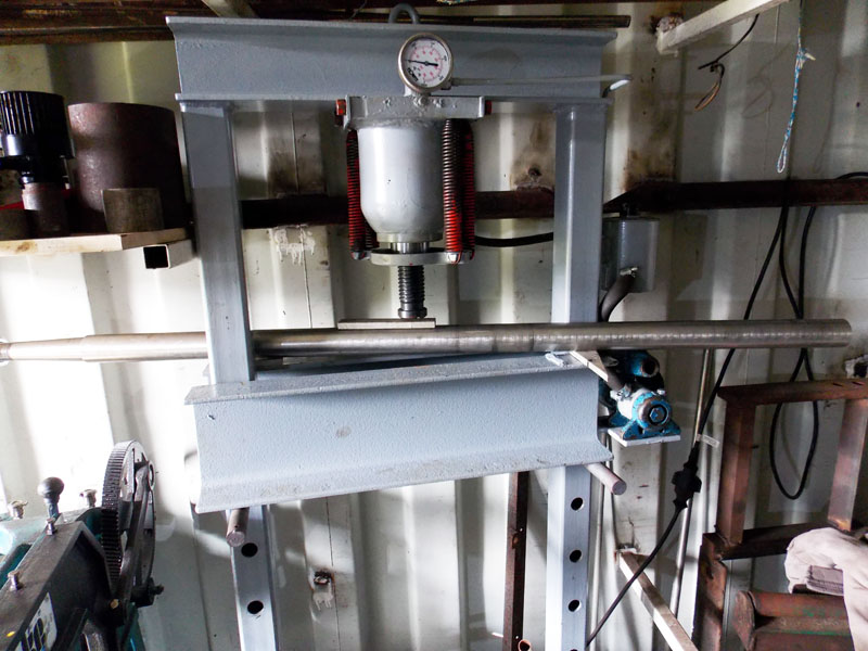
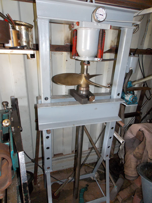
I made this little press jig for the job. Pressing the pulley flange onto the motor.
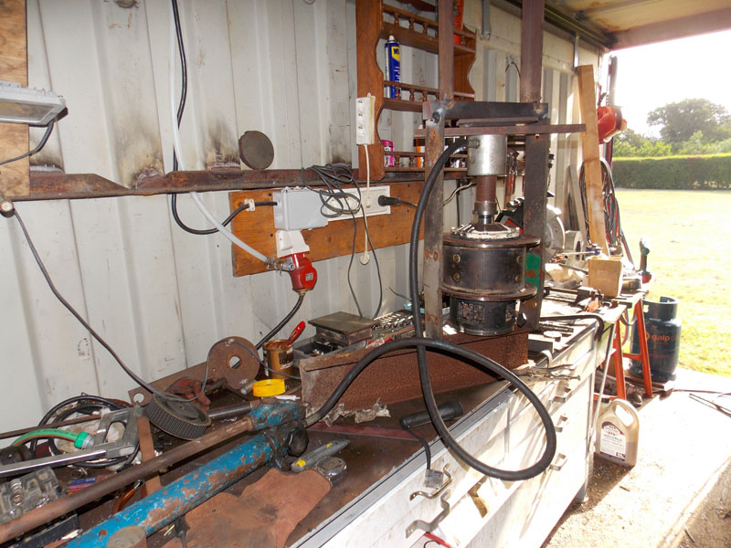
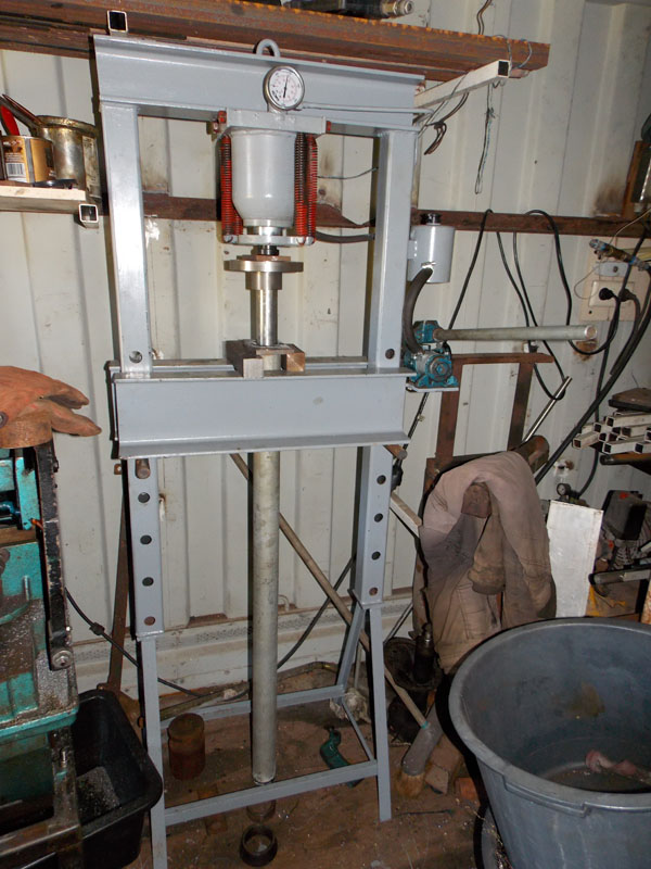
Flipped over pressingt the fan adaptor onto the armature shaft.
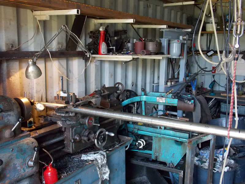
I used a surveying laser to line up the subshaft with the armature. A lage caliper and a strightedge got it aligned on the other 2 axis.
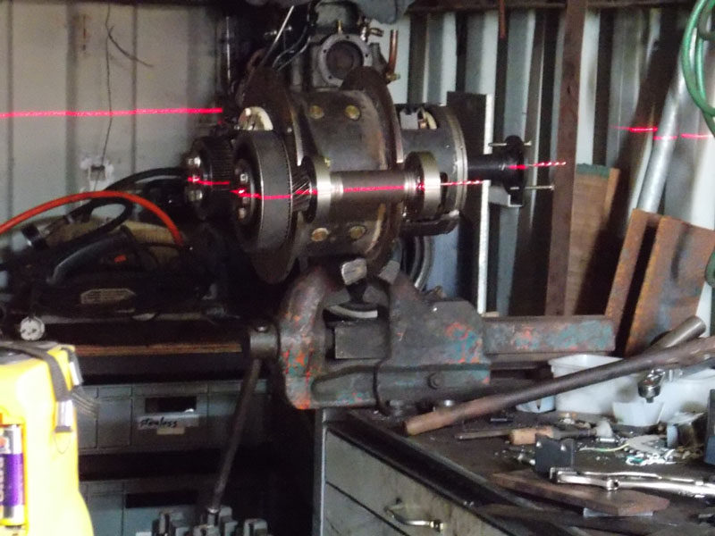
Final setup before welding the pivot tabs. Pulley bolts will be replaced with flush allen screws later.
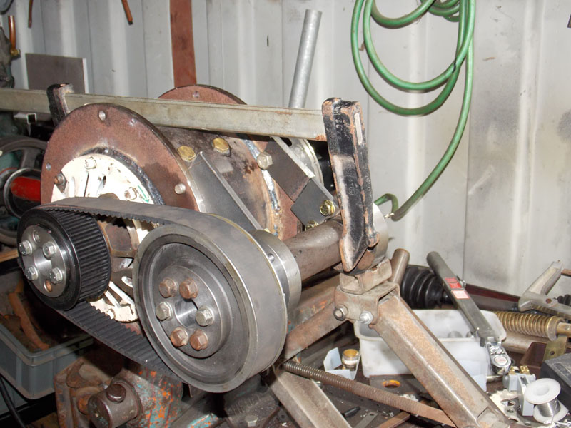
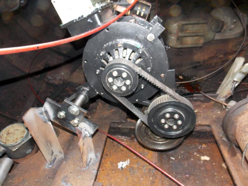
Subshaft with gear and pulley, the fan adaptor is visable on the back. I decided the bolt + pich sloted plates wouldn't be able to withstand the tension on the belt under load, so I made a better tensioner [see below].
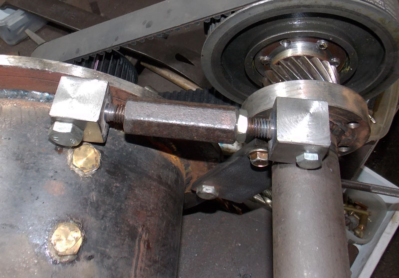
This is more like it; a left thread, a right thread, bolts and nut are hard steel, made on my lathe.
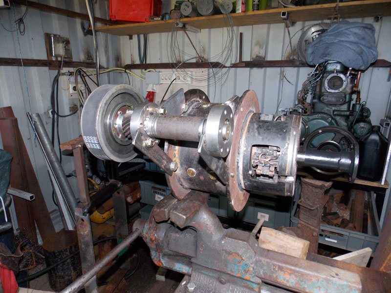
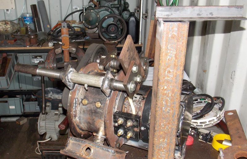
Here I've added a mounting for the whole assembly, a tube on the motor and a matching mild steel rod to be welded into the boat. In the foreground is the mounting jig. The square tube will be clamped to the propeller shaft flange, and the pivot rod set in the small agle steel, then welded to the boat somehow. This will ensure the motor is in line with the propshaft. after that it can be slid forward or back and locked in place with screw collars. the whole thing will pivot up to disengage the driving gear when the diesel motor is in use. Full speed on the diesel would overspeed the electric motor if it's still engaged. The small square plate with 3 bolts is removed to allow the motor assembly to be slid on or off of the mounting rod after the mounts are all welded in.
the idea is to do as much prep work as possible in the workshop, because time at the boat is expensive for me.
Control box cooling plate visible at the bottom. ICE engine on the bench in the background.
The motor came with the connection block at right with 4 stud holes, but only 2 studs. Reversing the current on a series motor will not change the direction, you have to change the direction of current on the field OR the armature.
I made the 2 bolts at the bottom from brass rod opened the internal wiring, and soldered to the new connections.
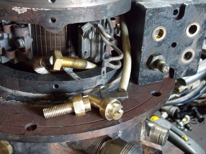
Brass insert for temperature feeler in the water jacket. These details are time consuming, but like I said, temperature is everything with this sort of machine.
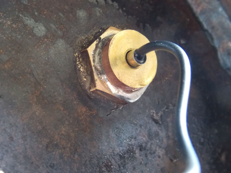
This is the other heat sensor for the air coming out of the interior. This should give me some indicator of the aramature temperature. I wanted it isolated from the metal, so I made this little clip from some leftover polycarbonate.

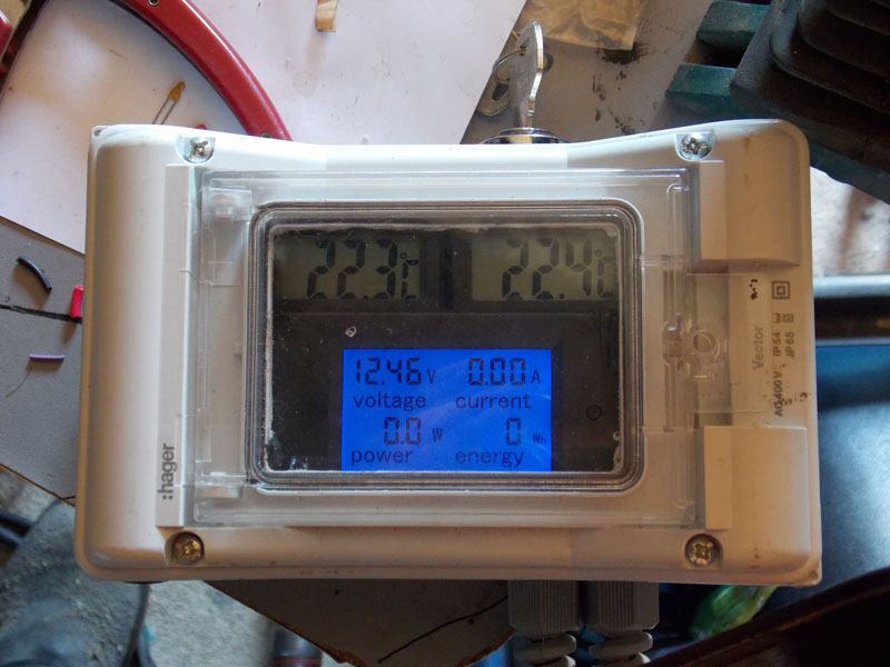
This is the first instrument box I made; the power meter is very cheap, the thermoometers less than a euro each. I made a regulated power supply for them so they run from the boat electrics instead of internal batteries.
My plan was to use the same control the diesel engine uses to operate the electric, I thought without the diesel engine running there would be no hydraulic pressure in the gearbox and the shaft would stay in neutral. I was wrong; it doesn't lock up but there's a lot of resistance to turning the shaft when in gear, even without the engine runnng. So I made another box with direction and speed control. Here it's connected to 12v for testing, the system will be 48vdc.
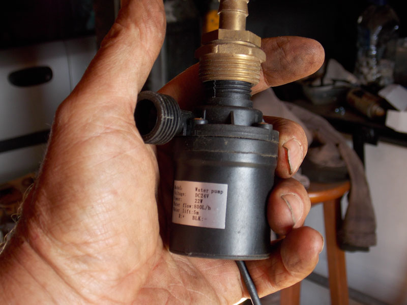
I bought 2 of these 24v waterpumps from ebay; in series they'll work on system voltage, 48v. One for raw water and one for glycol water. I tested them, they do work as advertised. Excitable little things.
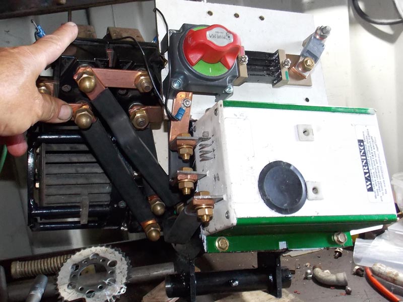
All assembled and ready to ship to the ship. I've added a rotary power switch, the shunt for the power meter, and a fuse. Under my hand is the big Allbright reversing relay [it also handles on/off]. I made the connetion bars from copper strip, it's a bit overkill.
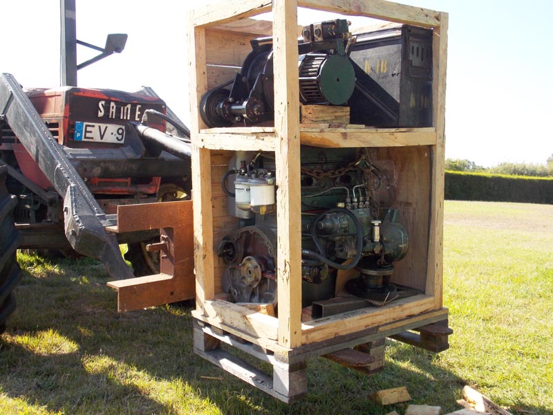
In the crate with the rebuilt diesel engine. 350kg, 2,500km to Amsterdam, point to point, only 120 euros.
Under the diesel motor, you can see the prop flange I took from the boat, now with the driving gear added.
In the boat in the water in Amsterdam; the alignment jig clamped to the thrust bearing flange, the mount rod clpamed to that with vicegrips while welding the braces in place. I might have a little fire going on too.
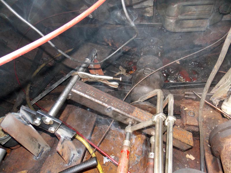
In this picture, I've added one of the lock collars to the mount shaft, and bolted on the driving gear / drive shaft adapter for the diesel motor. The shaft end plate is removed so the electric motor assembly can be slid into place.
And I put the fire out.
The motor assembly slid into place, the forward lock collar and end plate attached too. There will be a simple lever to lift the driving gear up to disengage the electric drive when using the 36HP Mercedes OM636 diesel engine.
Veiw from above.
I trialed the system with 2 start batteries [24v] and the drive works, and very smooth too.
I haven't finished the cooling system, and I still need a battery and a battery charger.
But I have a problem.
When I was building the motor in my workshop, I had no access to the boat. I thought the shaft turned the other way. The electric drive is reversable, but the cooling fan and 'timing' of the brushes like the original direction.
So I mounted the assembly the other way around, and there is a clearance problem with the diesel drive shaft.

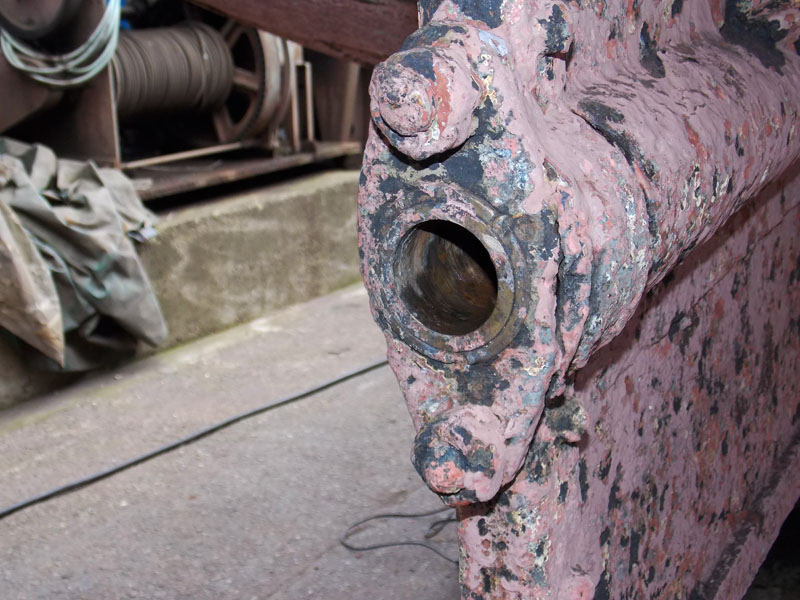
The boat was schedualed for haulout, and there were a couple of nasty surpises in wait. The propeller collar was split, and the ancient mild steel shaft is too corroded to mount a new one to.
Also, the hull needs a lot of new plate.
The logical move is to scrap the whole thing. The money I have to invest is equal or more than the likely value of the vessel after I complete it.
I made a bargain with the shipyard, to replate the hull when they have a lull in work. I removed the bearing block and brought it home, because it wouldn't hold oil. I found an old but unused prop on ebay that turns the other way. That will let me remount the motor as I origonaly intended, and solve the clearance problem.
My plan was to return in September 2020, but the Covid 19 pandemic changed my mind.
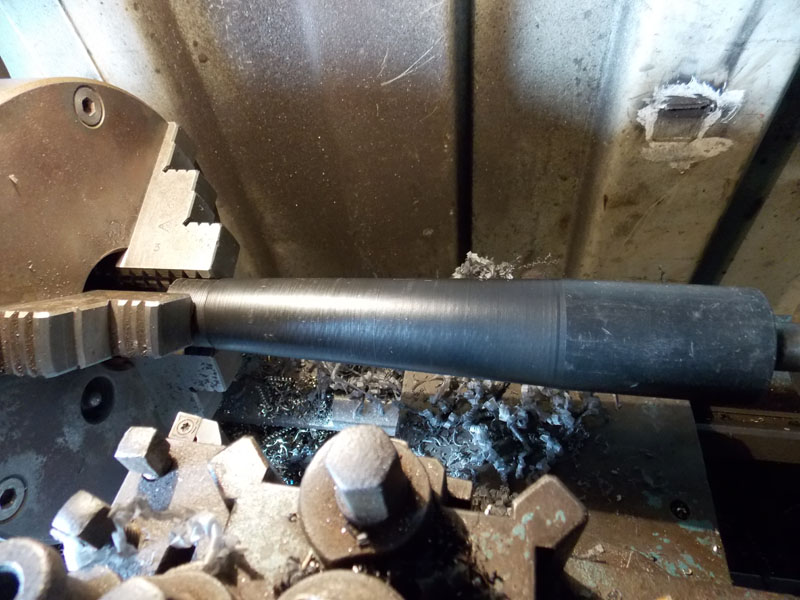
At my workshop in Portugal, I made a new stainless steel propshaft on my little lathe. Here I'm centering it on a welded peice of mild steel rod that will be cut off later.
Here I've cut the cone for the new prop. since the shaft is crazy oversized, it has a step in it. I also cut a keyway using my lathe.
Since this page is mostly about the electric conversion, I won't go into the details of the machining. Ok, I will but I'll put it at the bottom of this rather long page.
During the first test in Amsterdam, I realized that my plan to use the morse direction control that's connected to the old gearbox won't work for the electric drive, so I've made a new control box from some parts I had lying around.
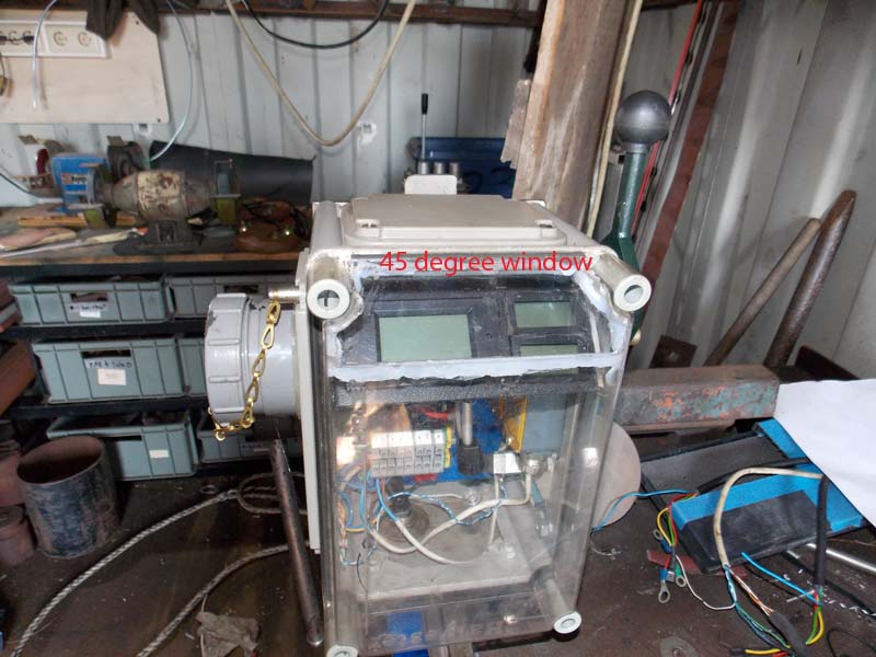
The electric panels from my first box [seen above] are fitted in, I fabricated a lever for a single stick control.
The capped pipe on the left side coveres the key switch, so it can be sealed up when not in use.
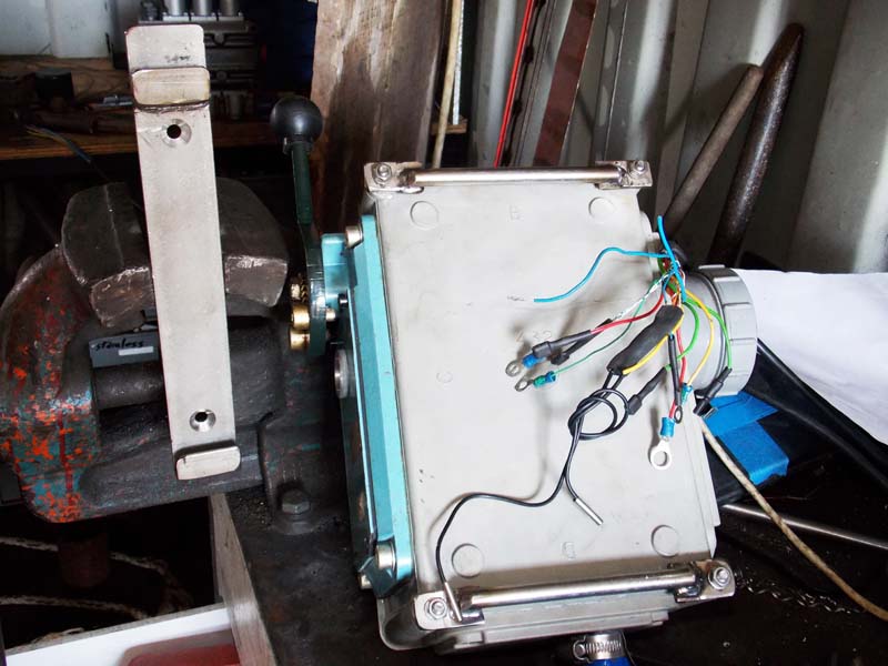
I made a quick mount bracket from stainless; rods across the back of the control box hook onto a bracket that will be left outside.
When the boat is not in use, the control box can be stowed below out of the weather.
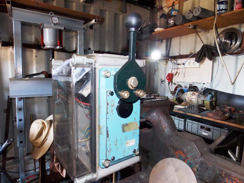
In these 3 picures, you can see how it works; a cam activates the forward or reverse limit switch, which energizes the apropriate coil of the Albright relay, while the link is rotating the potmeter to operate the AXE electronic control.
The relay coils are a bit beefy, at 1 amp + 48V, so a fairly large spring loaded limit switch is required.

I used a plate with asealed through shaft I found at a flea market long ago. I fabricated the lever from a bit of steel plate and made the knob from Delrin plastic. The 2 lower bolts are for the limit stops.
Well, that's as far as I've gotten in Septemeber 2020. The control box has been bench tested; with the new prop and propshaft, and the repaired ancient bearing block it's ready to ship to Netherlands to be installed into the boat.
The motor was installed and priliminarliy tested with 2 start batteries, but a real battery block and charging system are still needed.
A few pictures of the machining work on the 45mm propeller shaft.
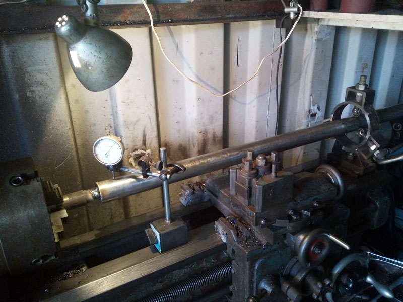
When I got it onto the lathe, I found it was bent. So I made a test jig and managed to straighten it in the press. This is tricky slow work, but in the end it only took a few hours to get it within .015mm, and I'm quite pleased.
It only needed a few tons. Protected against damage with aluminum plates.
Making a test cone in delron plastic. The propeller is factory bored at 10:1. I used a dial indicator to get the compound set at the correct angle. It took a while. Plastic is cheap, 318 stainless is not.
I have the weight supported by a stretch cord while the shaft is mounted sideways to cut the keyway. This is very much NOT the right way to do this job, but I did it anyway.
Getting it mounted accurately took a lot of thought and a lot of time. The cutting went well. I used a boring tool in a 4-jaw chuck, and made some test cuts in scrap first.
With prop and nut. I used a ready-made 30mm nut and added a collar. A cross bar will be weled across the tail to lock it in place after it's all fitted into the boat. The mild steel that I welded to the end for mounting the shaft in the lathe is now cut off.

Just a little push to get it apart again.
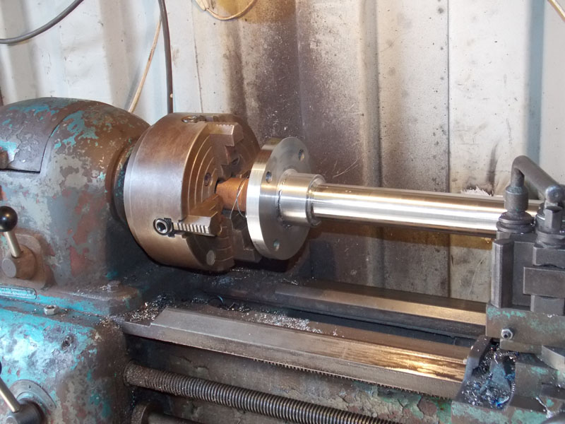
Pressing the flange on the inboard end with my home made press. I had to make a jig from pipe for the job.
Finishing and truing the inboard flange after welding [even though it was pressed at 10 tons] The flange is mild steel, the shaft is stainless 318
Another complication; the cutlass bushing on the old boat has a tapered bore. the old shaft was cut tapered to match; a very strange setup that no one seems to have seen before. The boat is 100 years old, I don't know if the prop tunnel was made later but it is rivetted in. So it's pre-war.
The bushing is 44-45mm on the inner and, and 42mm at the outer end. I just need to bore it out to 45.1 mm.
I have a plan...